

Description
M15 Pinpoint Nozzle styles afford the absolute minimum gate vestige possible. They are used when it is necessary to gate directly into the part being molded. The pinpoint nozzle features a field replaceable tip that can be easily changed by the customer if necessary. It performs well when processing unfilled resins. Hardened tip inserts are available as an option when it is necessary to mold filled resins.
When using the pinpoint nozzle, all necessary tip clearances are machined into the mold cavity by the customer. This method allows only a small pinpoint mark to be left on the part after molding.

Nozzle Body Section

| Part Number | Length "L" (mm) | Length "L" (in) |
|---|---|---|
| M15-NZ-P4-R2 | 31.5 | 1.240 |
| M15-NZ-P5-R2 | 44.2 | 1.740 |
| M15-NZ-P6-R2 | 56.9 | 2.240 |
| M15-NZ-P7-R2 | 69.6 | 2.740 |
| M15-NZ-P8-R2 | 82.3 | 3.240 |
| M15-NZ-P9-R2 | 95.0 | 3.740 |
| M15-NZ-P10-R2 | 107.7 | 4.240 |
| M15-NZ-P11-R2 | 120.4 | 4.740 |
| M15-NZ-P12-R2 | 133.1 | 5.240 |
| M15-NZ-P13-R2 | 145.8 | 5.740 |
| M15-NZ-P14-R2 | 158.5 | 6.240 |
| M15-NZ-P15-R2 | 171.2 | 6.740 |
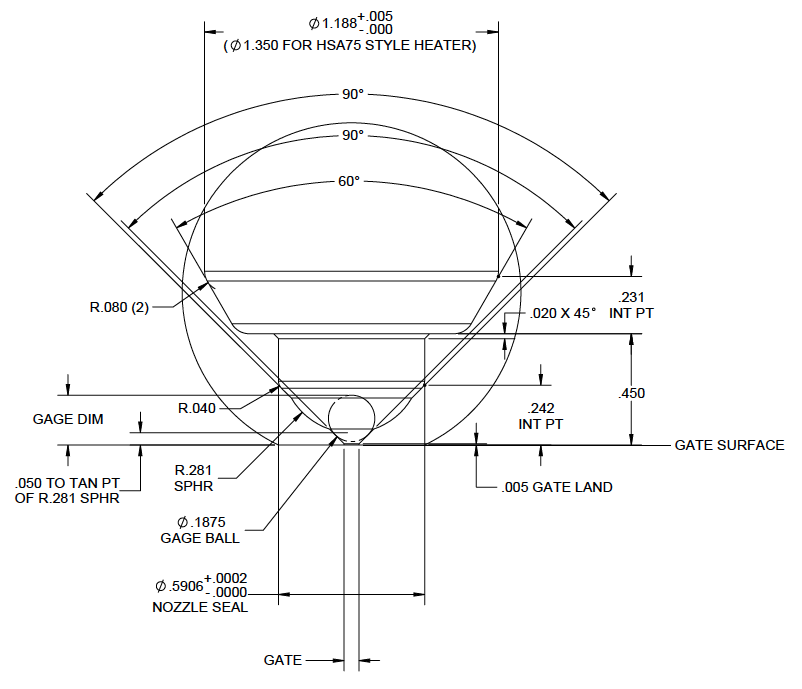
Gate Well Detail
| Gate Ø | Gage Dimension |
|---|---|
| 0.0250 | 0.2188 |
| 0.0260 | 0.2183 |
| 0.0270 | 0.2178 |
| 0.0280 | 0.2173 |
| 0.0290 | 0.2168 |
| 0.0300 | 0.2163 |
| 0.0310 | 0.2158 |
| 0.0320 | 0.2153 |
| 0.0330 | 0.2148 |
| 0.0340 | 0.2143 |
| 0.0350 | 0.2138 |
| 0.0360 | 0.2133 |
| 0.0370 | 0.2128 |
| 0.0380 | 0.2123 |
| 0.0390 | 0.2118 |
| 0.0400 | 0.2113 |
| 0.0410 | 0.2108 |
| 0.0420 | 0.2103 |
| 0.0430 | 0.2098 |
| 0.0440 | 0.2093 |
| 0.0450 | 0.2088 |
| 0.0460 | 0.2083 |
| 0.0470 | 0.2078 |
| Gate Ø | Gage Dimension |
|---|---|
| 0.0480 | 0.2073 |
| 0.0490 | 0.2068 |
| 0.0500 | 0.2063 |
| 0.0510 | 0.2058 |
| 0.0520 | 0.2053 |
| 0.0530 | 0.2048 |
| 0.0540 | 0.2043 |
| 0.0550 | 0.2038 |
| 0.0560 | 0.2033 |
| 0.0570 | 0.2028 |
| 0.0580 | 0.2023 |
| 0.0590 | 0.2018 |
| 0.0600 | 0.2013 |
| 0.0610 | 0.2008 |
| 0.0620 | 0.2003 |
| 0.0630 | 0.1998 |
| 0.0640 | 0.1993 |
| 0.0650 | 0.1988 |
| 0.0660 | 0.1983 |
| 0.0670 | 0.1978 |
| 0.0680 | 0.1973 |
| 0.0690 | 0.1968 |
| 0.0700 | 0.1963 |
Minimum Spacing Requirements
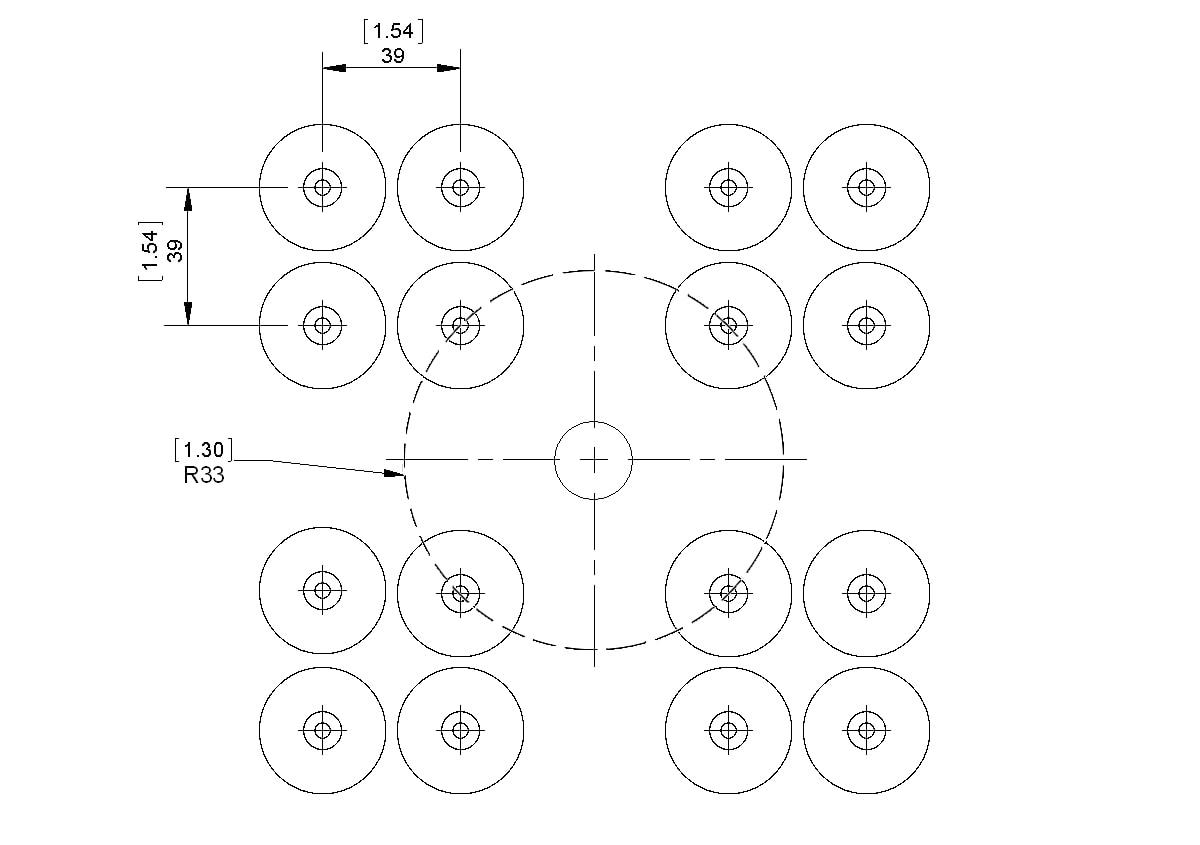
NOTE: Nozzle centerlines must be located at least 33mm [1.30″] radially away from the centerline of the nozzle interface.