
Explore All Our Nozzles
Overview
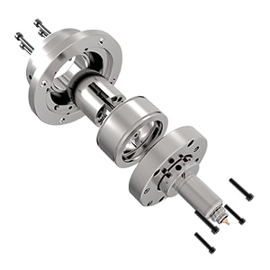
The Polyshot Hot Runner Manifold system is an exceptional, pre-engineered hot runner system designed specifically for the injection molding process. The hot runner system is shipped fully assembled, tested, and ready to be bolted directly onto the injection mold. It is also available as a standalone unit for moldmakers who prefer molding their own hot half plates.
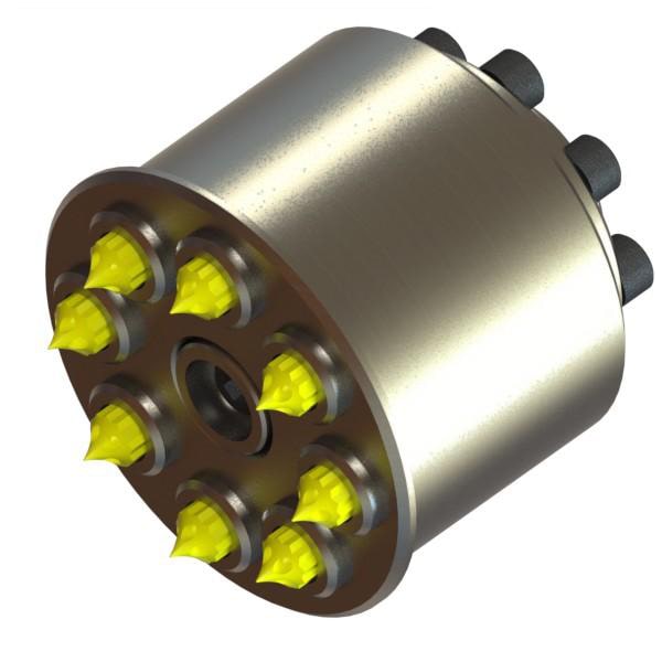
The system utilizes advanced components for hot runner systems, including molding with replaceable flexible tubular heaters. These heated components are designed to fit the hot runner’s grooves perfectly and can be replaced by the customer in the field if necessary. Each nozzle in the hot runner system is heated and controlled individually by its own heater and thermocouple, ensuring precise control over the injection points and consistent flow of plastic melt for shot-to-shot performance.
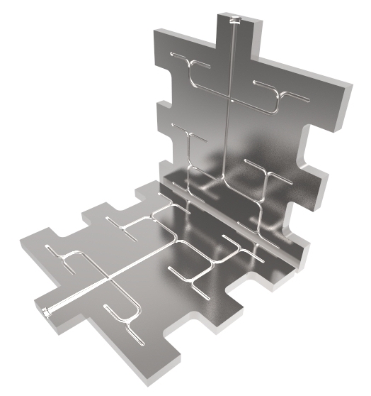
Our proprietary hot runner technology ensures balanced flow through the construction of layered systems and our in-house vacuum brazing process. This hot runner technology allows for large, sweeping arc flow channels with gradually changing diameters, ensuring smooth material flow and enhanced longevity even with filled resins. The use of different nozzles enhances the system’s flexibility, allowing it to handle various resin types efficiently.
Description
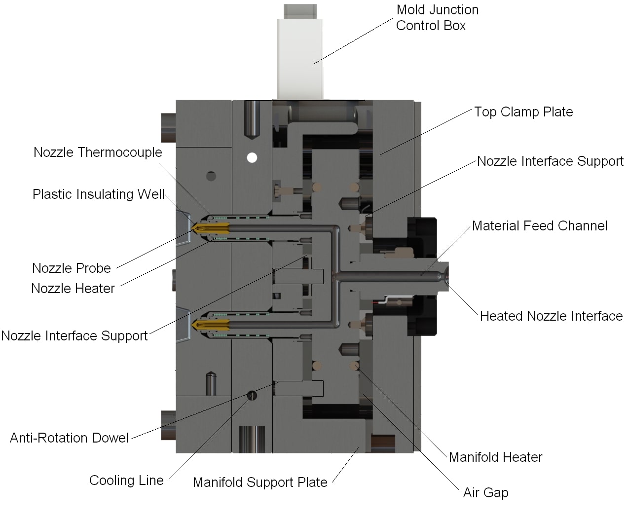
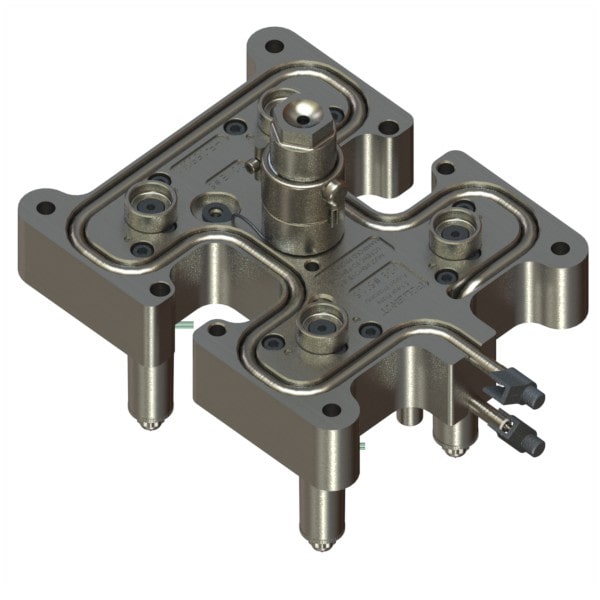
Nozzle alignment: Hot runners are usually designed to accommodate stress-free thermal expansion. The center of the system is securely fixed in the injection molding process by the nozzle interface engaged to the top clamp plate and a dowel pin fitting into the support plate. As the hot runner heats up and expands, it can slide across the top of the nozzle seats, ensuring perfect alignment of the feed holes in the manifold and nozzles when fully heated.
Flow channels: Polyshot’s hot runner systems use proprietary plate fusion technology to provide smooth material flow paths without sharp corners or holding areas. This feature is especially beneficial in family molds or typically unbalanced hot runners. The design for these hot runners also allows the manifold’s flow channel sizes to be adjusted without compromising quality or balance, a feature not achievable with standard turn plug designs. The result is improved cycle time and product consistency.
Details
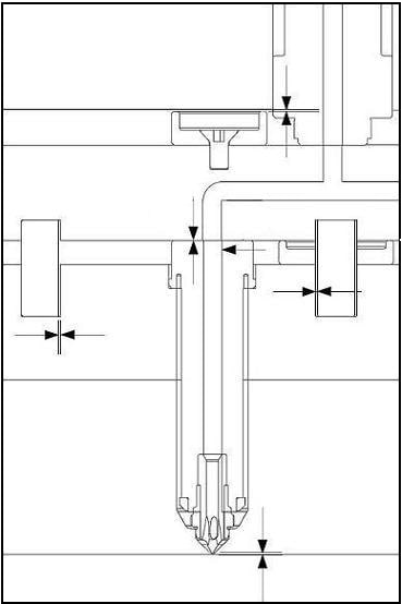
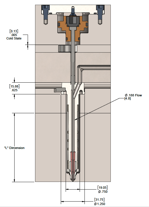
Thermal expansion: The illustration above demonstrates that Polyshot’s engineers carefully calculate thermal expansion in the hot runner system, ensuring that the customer does not need to worry about this aspect.
Nozzle sealing: Nozzle sealing is achieved both mechanically and thermally. The mechanical seal is accomplished by bolting each nozzle to the hot runner using two socket head cap screws. As the system heats up, the thermal expansion across the hot runner components allows a predetermined amount of preload on the nozzle seat. This combination creates a reliable, trouble-free seal.
Electrical requirements: All Polyshot manifold hot runners systems operate at 208 to 240 VAC. Each nozzle draws a maximum of 2 amps, and the total amp draw is determined by the number of nozzles and the size of the hot runner manifold.
The Polyshot hot runner system offers a balance of quality, performance, and dependability, making it an excellent solution for enhancing the efficiency and precision of any injection molding process. With its advanced hot runner components and technology, the system ensures a constant temperature throughout the injection molding process, reducing cycle time and improving part quality. Different nozzles can be used to accommodate a variety of plastic melt types, ensuring flexibility in production.
For more information on our vacuum brazing services or to discuss your specific hot runner needs, please contact us at sales@polyshot.com. The typical turnaround time for this process is about 2 to 3 weeks.
10M Pinpoint Nozzle
Description
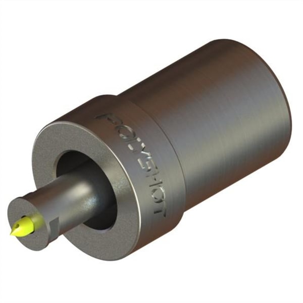
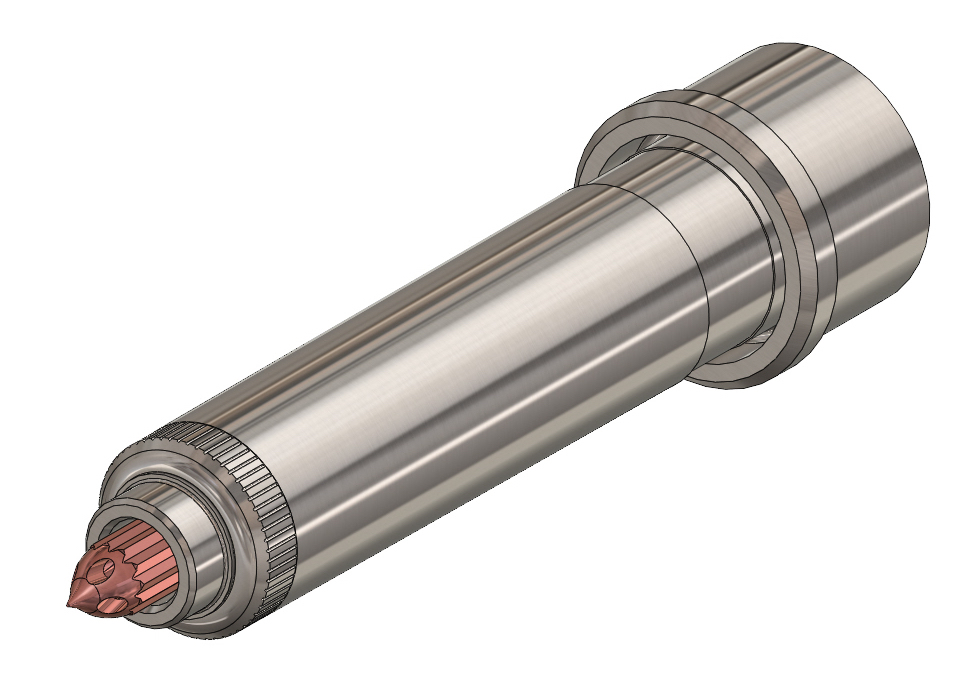
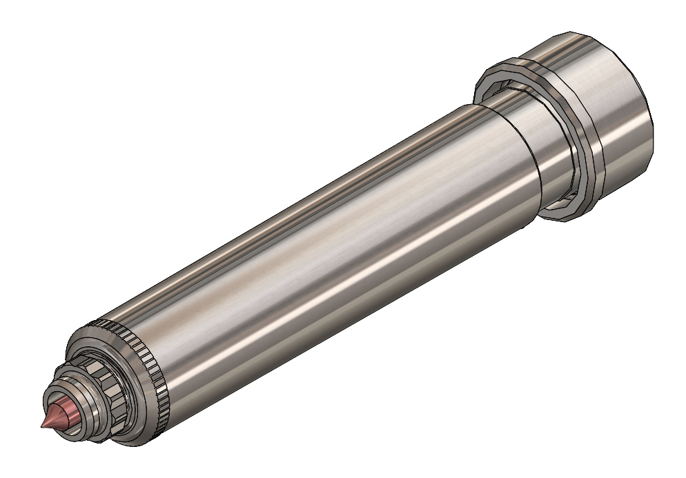
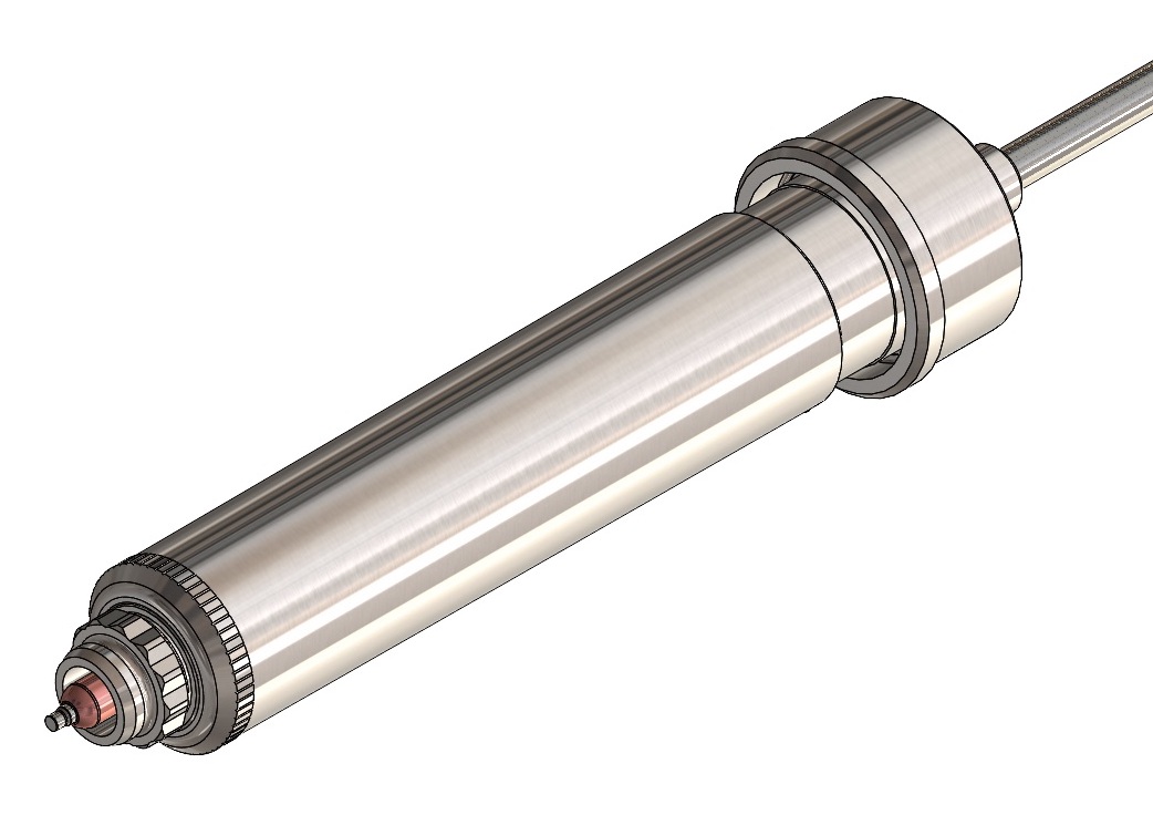
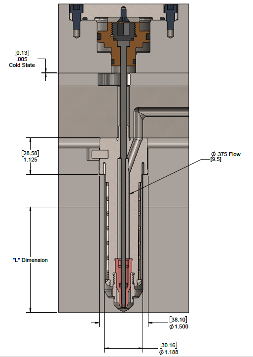
10M Pinpoint Nozzle styles afford the absolute minimum gate vestige possible. They are used when it is necessary to gate directly into the part being molded. The pinpoint nozzle features a field replaceable tip that can be easily changed by the customer if necessary. It performs well when processing unfilled resins. Hardened tip inserts are available as an option when it is necessary to mold filled resins.
When using the pinpoint nozzle, all necessary tip clearances are machined into the mold cavity by the customer. This method allows only a small pinpoint mark to be left on the part after molding.
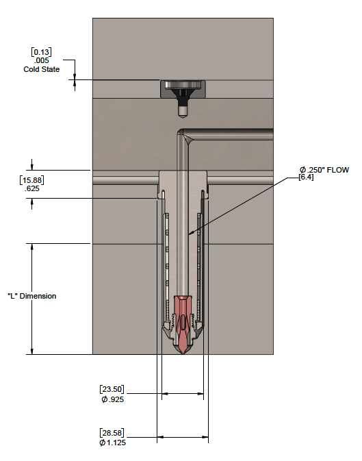
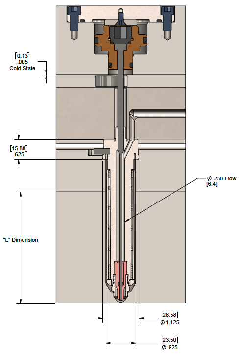
Nozzle Body Section
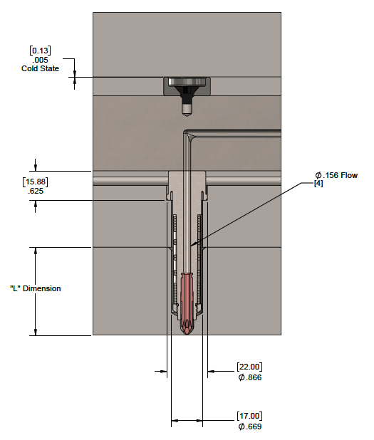
| Part Number | Length "L" (mm) | Length "L" (in) |
|---|---|---|
| P-10M-NZ-P3 | 22.2 | 0.8748 |
| P-10M-NZ-P4 | 34.9 | 1.3748 |
| P-10M-NZ-P5 | 47.6 | 1.8748 |
| P-10M-NZ-P6 | 60.3 | 2.3748 |
| P-10M-NZ-P7 | 73.0 | 2.8748 |
| P-10M-NZ-P8 | 85.7 | 3.3748 |
| P-10M-NZ-P9 | 98.4 | 3.8748 |
| P-10M-NZ-P10 | 111.1 | 4.3748 |
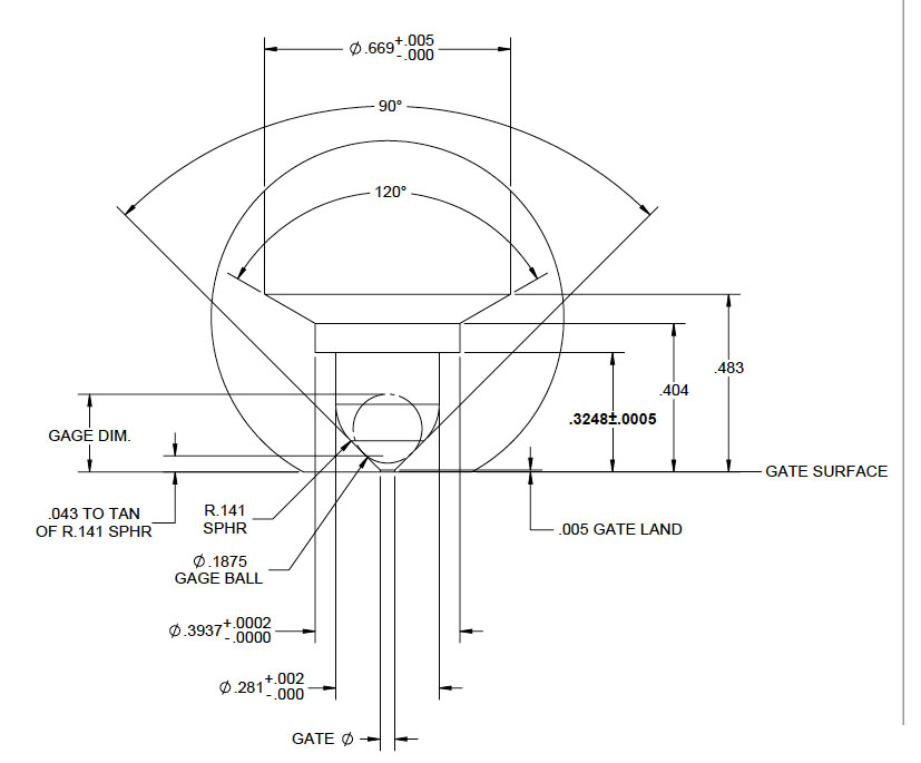
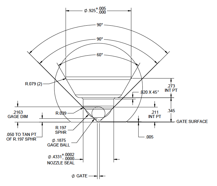
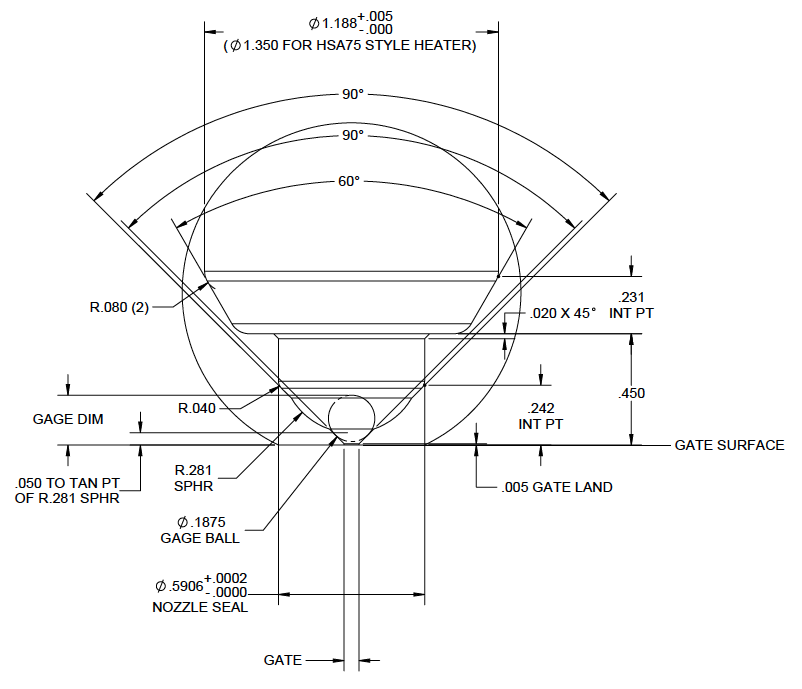
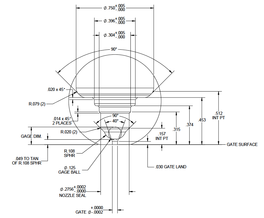
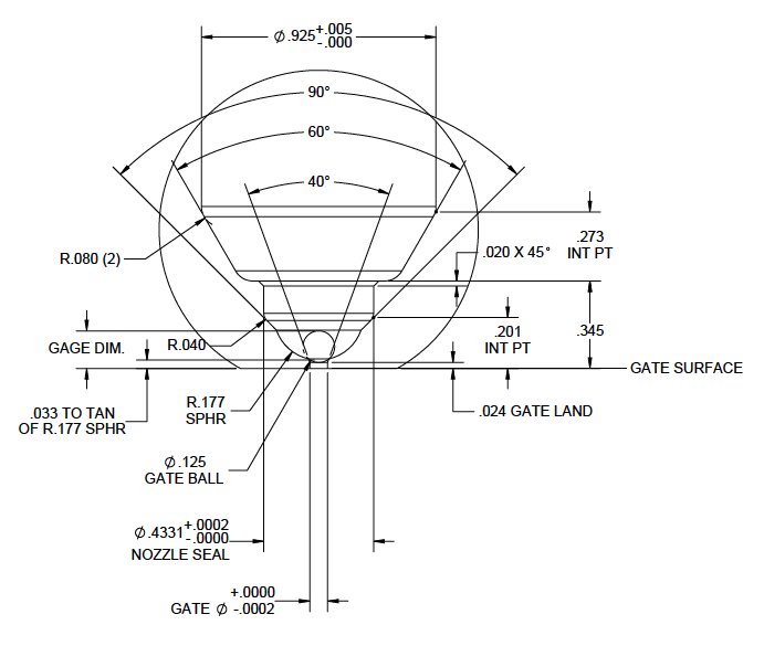
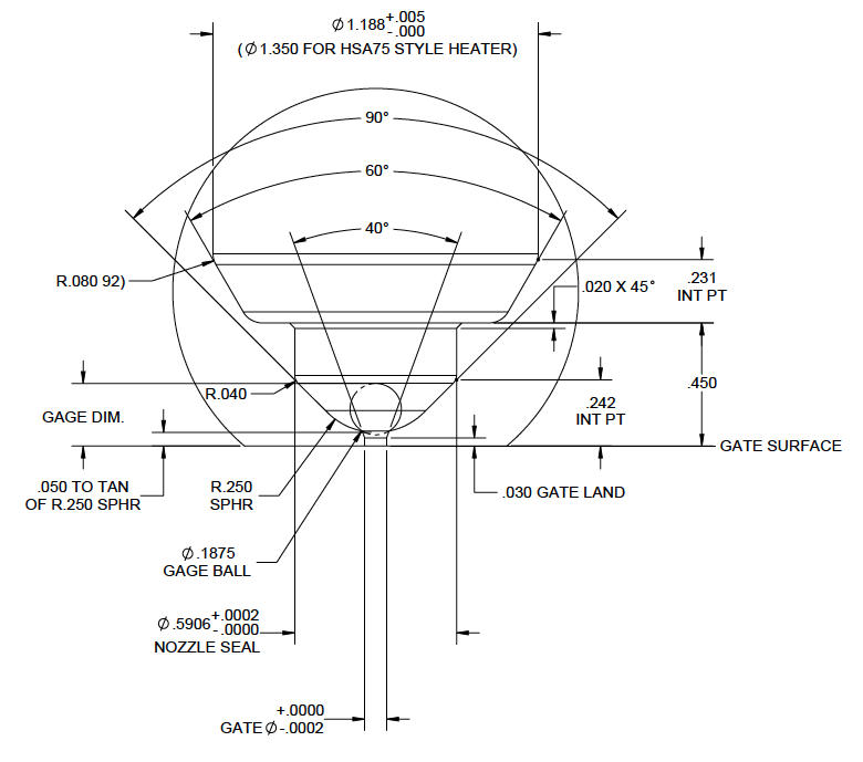
Gate Well Detail
| Gate Ø | Gage Dimension |
|---|---|
| 0.0250 | 0.2188 |
| 0.0260 | 0.2183 |
| 0.0270 | 0.2178 |
| 0.0280 | 0.2173 |
| 0.0290 | 0.2168 |
| 0.0300 | 0.2163 |
| 0.0310 | 0.2158 |
| 0.0320 | 0.2153 |
| 0.0330 | 0.2148 |
| 0.0340 | 0.2143 |
| 0.0350 | 0.2138 |
| 0.0360 | 0.2133 |
| 0.0370 | 0.2128 |
| 0.0380 | 0.2123 |
| 0.0390 | 0.2118 |
| 0.0400 | 0.2113 |
| 0.0410 | 0.2108 |
| 0.0420 | 0.2103 |
| 0.0430 | 0.2098 |
| 0.0440 | 0.2093 |
| 0.0450 | 0.2088 |
| 0.0460 | 0.2083 |
| 0.0470 | 0.2078 |
| Gate Ø | Gage Dimension |
|---|---|
| 0.0480 | 0.2073 |
| 0.0490 | 0.2068 |
| 0.0500 | 0.2063 |
| 0.0510 | 0.2058 |
| 0.0520 | 0.2053 |
| 0.0530 | 0.2048 |
| 0.0540 | 0.2043 |
| 0.0550 | 0.2038 |
| 0.0560 | 0.2033 |
| 0.0570 | 0.2028 |
| 0.0580 | 0.2023 |
| 0.0590 | 0.2018 |
| 0.0600 | 0.2013 |
| 0.0610 | 0.2008 |
| 0.0620 | 0.2003 |
| 0.0630 | 0.1998 |
| 0.0640 | 0.1993 |
| 0.0650 | 0.1988 |
| 0.0660 | 0.1983 |
| 0.0670 | 0.1978 |
| 0.0680 | 0.1973 |
| 0.0690 | 0.1968 |
| 0.0670 | 0.1963 |
Standard Gate Well
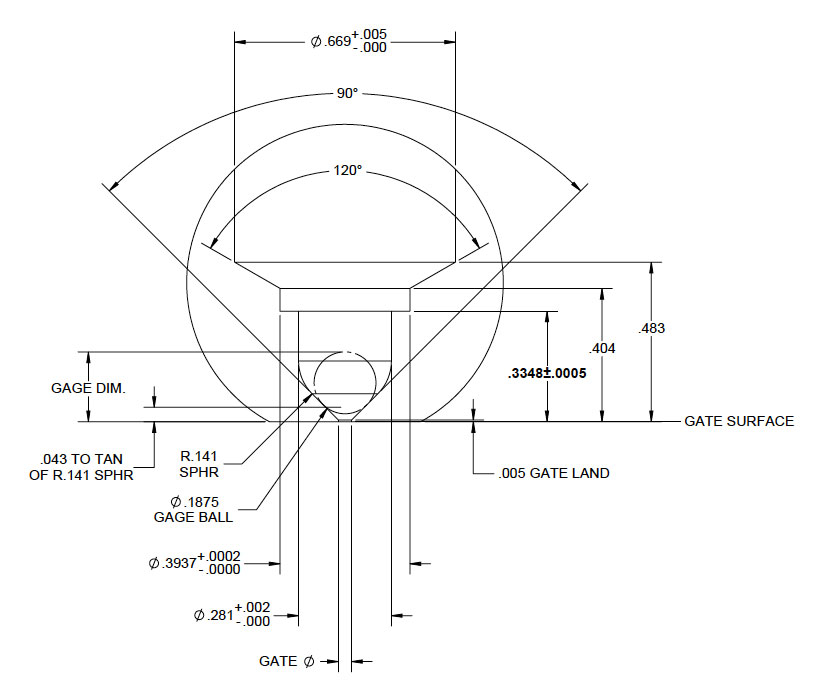
Gate Well for PP & PE Only
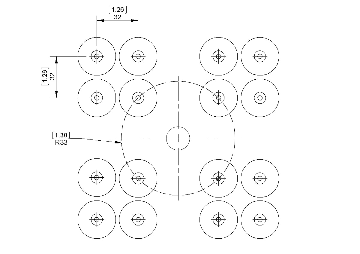
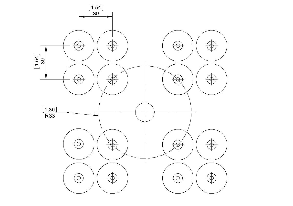
Minimum Spacing Requirements
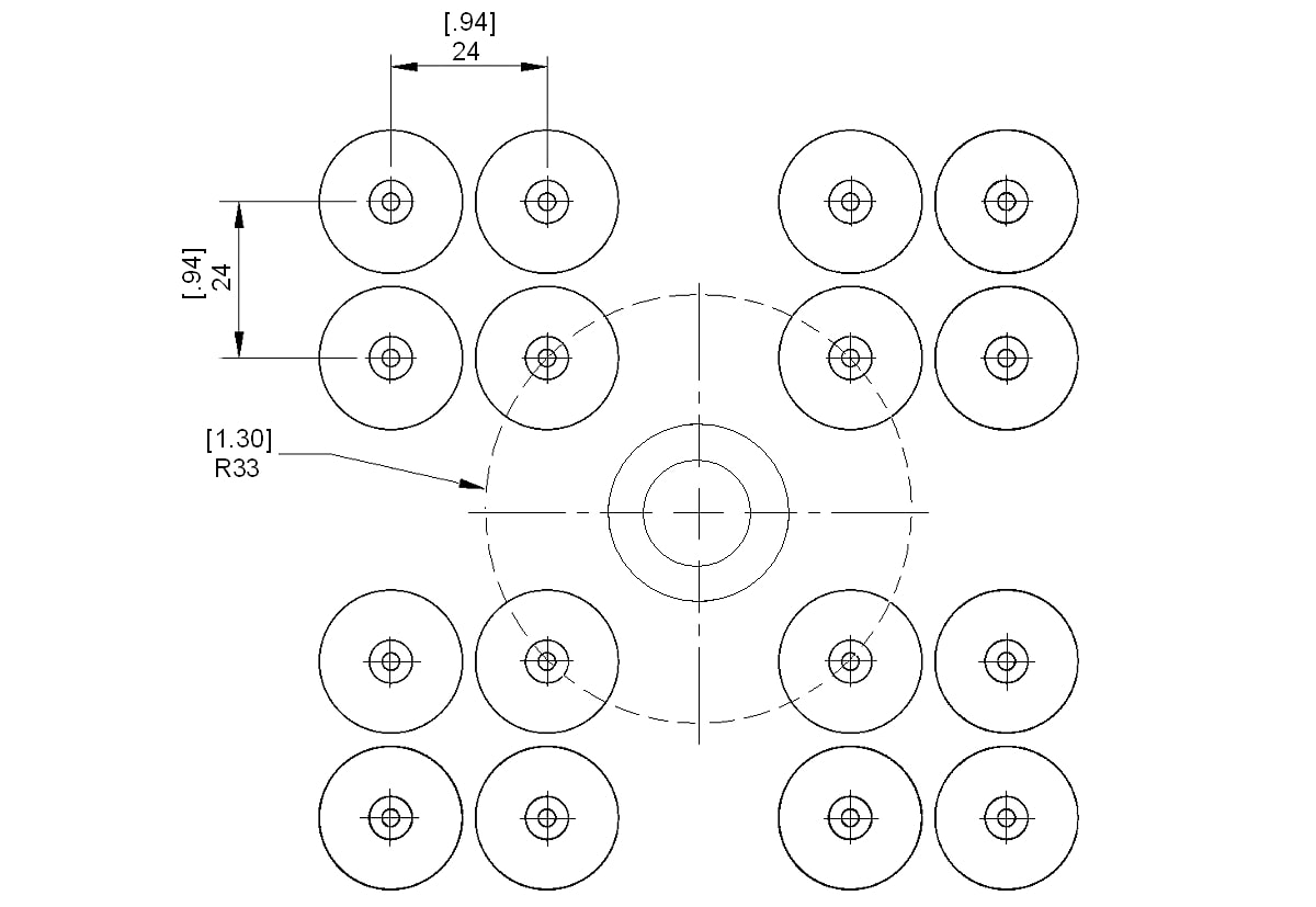
NOTE: Nozzle centerlines must be located at least 33mm [1.30″] radially away from the centerline of the nozzle interface.
M11 Pinpoint Nozzle
Description
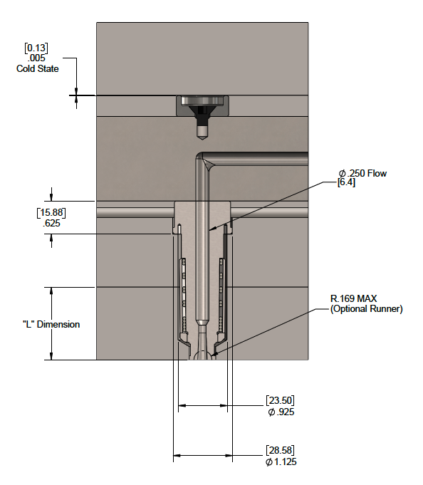
M11 Pinpoint Nozzle tip style uses a pinpoint gate design to allow the absolute minimum gate vestige possible. The gate well area is machined directly into the mold cavity by the mold maker. This nozzle can be used for most resins with part sizes of 30 grams or less. Can run glass or mineral filled resins with an optional tip.
Nozzle Body Section
| Part Number | Length "L" (mm) | Length "L" (in) |
|---|---|---|
| M11-NZ-P3-R2 | 24.2 | 0.951 |
| M11-NZ-P4-R2 | 36.9 | 1.451 |
| M11-NZ-P5-R2 | 49.6 | 1.951 |
| M11-NZ-P6-R2 | 62.3 | 2.451 |
| M11-NZ-P7-R2 | 75.0 | 2.951 |
| M11-NZ-P8-R2 | 87.7 | 3.451 |
| M11-NZ-P9-R2 | 100.4 | 3.951 |
| M11-NZ2-P10 | 113.1 | 4.451 |
| M11-NZ2-P11 | 125.8 | 4.951 |
| M11-NZ2-P12 | 138.5 | 5.451 |
| M11-NZ2-P13 | 151.2 | 5.951 |
| M11-NZ2-P14 | 163.9 | 6.451 |
| M11-NZ2-P15 | 176.6 | 6.951 |
Gate Well Detail
| Gate Ø | Gage Dimension |
|---|---|
| 0.0250 | 0.2188 |
| 0.0260 | 0.2183 |
| 0.0270 | 0.2178 |
| 0.0280 | 0.2173 |
| 0.0290 | 0.2168 |
| 0.0300 | 0.2163 |
| 0.0310 | 0.2158 |
| 0.0320 | 0.2153 |
| 0.0330 | 0.2148 |
| 0.0340 | 0.2143 |
| 0.0350 | 0.2138 |
| 0.0360 | 0.2133 |
| 0.0370 | 0.2128 |
| 0.0380 | 0.2123 |
| 0.0390 | 0.2118 |
| 0.0400 | 0.2113 |
| 0.0410 | 0.2108 |
| 0.0420 | 0.2103 |
| 0.0430 | 0.2098 |
| 0.0440 | 0.2093 |
| 0.0450 | 0.2088 |
| 0.0460 | 0.2083 |
| 0.0470 | 0.2078 |
| Gate Ø | Gage Dimension |
|---|---|
| 0.0480 | 0.2073 |
| 0.0490 | 0.2068 |
| 0.0500 | 0.2063 |
| 0.0510 | 0.2058 |
| 0.0520 | 0.2053 |
| 0.0530 | 0.2048 |
| 0.0540 | 0.2043 |
| 0.0550 | 0.2038 |
| 0.0560 | 0.2033 |
| 0.0570 | 0.2028 |
| 0.0580 | 0.2023 |
| 0.0590 | 0.2018 |
| 0.0600 | 0.2013 |
| 0.0610 | 0.2008 |
| 0.0620 | 0.2003 |
| 0.0630 | 0.1998 |
| 0.0640 | 0.1993 |
| 0.0650 | 0.1988 |
| 0.0660 | 0.1983 |
| 0.0670 | 0.1978 |
| 0.0680 | 0.1973 |
| 0.0690 | 0.1968 |
| 0.0700 | 0.1963 |
Minimum Spacing Requirements
NOTE: Nozzle centerlines must be located at least 33mm [1.30″] radially away from the centerline of the nozzle interface.
M15 Pinpoint Nozzle
Description
M15 Pinpoint Nozzle styles afford the absolute minimum gate vestige possible. They are used when it is necessary to gate directly into the part being molded. The pinpoint nozzle features a field replaceable tip that can be easily changed by the customer if necessary. It performs well when processing unfilled resins. Hardened tip inserts are available as an option when it is necessary to mold filled resins.
When using the pinpoint nozzle, all necessary tip clearances are machined into the mold cavity by the customer. This method allows only a small pinpoint mark to be left on the part after molding.

Nozzle Body Section

| Part Number | Length "L" (mm) | Length "L" (in) |
|---|---|---|
| M15-NZ-P4-R2 | 31.5 | 1.240 |
| M15-NZ-P5-R2 | 44.2 | 1.740 |
| M15-NZ-P6-R2 | 56.9 | 2.240 |
| M15-NZ-P7-R2 | 69.6 | 2.740 |
| M15-NZ-P8-R2 | 82.3 | 3.240 |
| M15-NZ-P9-R2 | 95.0 | 3.740 |
| M15-NZ-P10-R2 | 107.7 | 4.240 |
| M15-NZ-P11-R2 | 120.4 | 4.740 |
| M15-NZ-P12-R2 | 133.1 | 5.240 |
| M15-NZ-P13-R2 | 145.8 | 5.740 |
| M15-NZ-P14-R2 | 158.5 | 6.240 |
| M15-NZ-P15-R2 | 171.2 | 6.740 |
Gate Well Detail
| Gate Ø | Gage Dimension |
|---|---|
| 0.0250 | 0.2188 |
| 0.0260 | 0.2183 |
| 0.0270 | 0.2178 |
| 0.0280 | 0.2173 |
| 0.0290 | 0.2168 |
| 0.0300 | 0.2163 |
| 0.0310 | 0.2158 |
| 0.0320 | 0.2153 |
| 0.0330 | 0.2148 |
| 0.0340 | 0.2143 |
| 0.0350 | 0.2138 |
| 0.0360 | 0.2133 |
| 0.0370 | 0.2128 |
| 0.0380 | 0.2123 |
| 0.0390 | 0.2118 |
| 0.0400 | 0.2113 |
| 0.0410 | 0.2108 |
| 0.0420 | 0.2103 |
| 0.0430 | 0.2098 |
| 0.0440 | 0.2093 |
| 0.0450 | 0.2088 |
| 0.0460 | 0.2083 |
| 0.0470 | 0.2078 |
| Gate Ø | Gage Dimension |
|---|---|
| 0.0480 | 0.2073 |
| 0.0490 | 0.2068 |
| 0.0500 | 0.2063 |
| 0.0510 | 0.2058 |
| 0.0520 | 0.2053 |
| 0.0530 | 0.2048 |
| 0.0540 | 0.2043 |
| 0.0550 | 0.2038 |
| 0.0560 | 0.2033 |
| 0.0570 | 0.2028 |
| 0.0580 | 0.2023 |
| 0.0590 | 0.2018 |
| 0.0600 | 0.2013 |
| 0.0610 | 0.2008 |
| 0.0620 | 0.2003 |
| 0.0630 | 0.1998 |
| 0.0640 | 0.1993 |
| 0.0650 | 0.1988 |
| 0.0660 | 0.1983 |
| 0.0670 | 0.1978 |
| 0.0680 | 0.1973 |
| 0.0690 | 0.1968 |
| 0.0700 | 0.1963 |
Minimum Spacing Requirements
NOTE: Nozzle centerlines must be located at least 33mm [1.30″] radially away from the centerline of the nozzle interface.
M10VG Valve Gate Nozzle
Description
M10VG Valve Gate Nozzle eliminates the gate vestige. They are used when it is necessary to gate directly into the part being molded without leaving a vestige. The valve gate nozzle features a field replaceable tip that can be easily changed by the customer if necessary. It performs well when processing unfilled, low temperature resins and is best for part sizes up to 5 grams. The valve pins can be actuated by pneumatics or hydraulics.
When using the valve gate nozzle, all necessary tip clearances are machined into the mold cavity by the customer. This method allows for the smallest witness mark to be left on the part after molding. The valve gate pin mark will resemble an ejector pin mark on the part.
Polyshot Accutrak Technology
Polyshot Accutrak Technology was developed to improve product quality in injection molded parts. The Accutrak design allows for quick and easy color changes. This reduces waste and down time.
Features include:
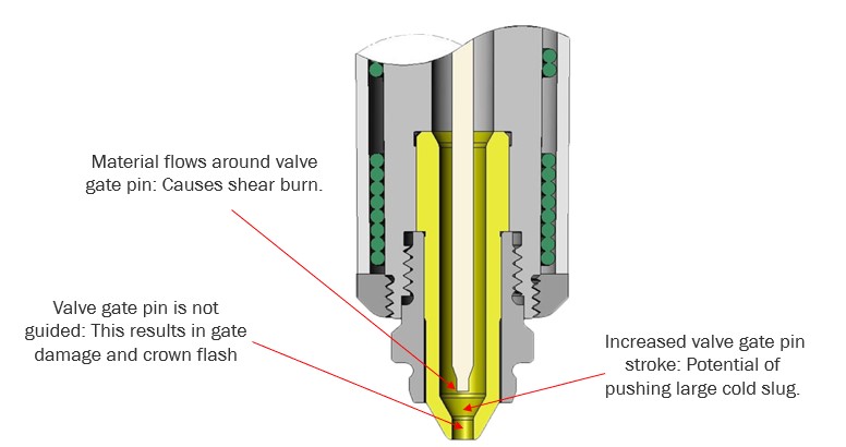
Burn-free gates, no black specks or streaks | Completely sweeps the gate well area clean each slot | Valve gate versions offer very short stroke reducing the hydraulic action in the gate area | Valve pin stays fully engaged and guided 100% of the time | Pinpoint style Accutraks are also available
Accutrak Valve Gate Technology
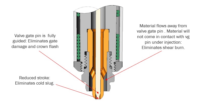
Conventional Valve Gate Technology
Nozzle Body Section
| Part Number | Length "L" (mm) | Length "L" (in) |
|---|---|---|
| M10VG-HFNZ-P4-R1 | 29.0 | 1.143 |
| M10VG-HFNZ-P5-R1 | 41.74 | 1.643 |
| M10VG-HFNZ-P6-R1 | 54.4 | 2.143 |
| M10VG-HFNZ-P7-R1 | 67.1 | 2.643 |
| M10VG-HFNZ-P8-R1 | 79.8 | 3.143 |
| M10VG-HFNZ-P9-R1 | 92.5 | 3.643 |
| M10VG-HFNZ-P10-R1 | 105.2 | 4.143 |
| M10VG-HFNZ-P11-R1 | 117.9 | 4.643 |
Gate Well Detail
| Gate Ø | Gage Dimension |
|---|---|
| 0.025 | 0.1726 |
| 0.026 | 0.1725 |
| 0.027 | 0.1724 |
| 0.028 | 0.1723 |
| 0.029 | 0.1722 |
| 0.030 | 0.1721 |
| 0.031 | 0.1720 |
| 0.032 | 0.1719 |
| 0.033 | 0.1718 |
| 0.034 | 0.1717 |
| 0.035 | 0.1716 |
| 0.036 | 0.1715 |
| 0.037 | 0.1714 |
| Gate Ø | Gage Dimension |
|---|---|
| 0.038 | 0.1713 |
| 0.039 | 0.1711 |
| 0.040 | 0.1710 |
| 0.041 | 0.1709 |
| 0.042 | 0.1707 |
| 0.043 | 0.1706 |
| 0.044 | 0.1704 |
| 0.045 | 0.1703 |
| 0.046 | 0.1701 |
| 0.047 | 0.1700 |
| 0.048 | 0.1698 |
| 0.049 | 0.1696 |
| 0.050 | 0.1695 |
Minimum Spacing Requirements
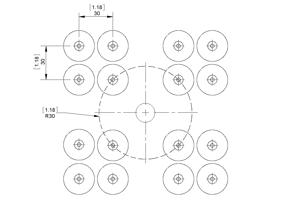
NOTE: Nozzle centerlines must be located at least 30mm [1.18″] radially away from the centerline of the nozzle interface.
M11VG Valve Gate Nozzle
Description
M11VG Valve Gate Nozzle eliminates the gate vestige. They are used when it is necessary to gate directly into the part being molded without leaving a vestige. The valve gate nozzle features a field replaceable tip that can be easily changed by the customer if necessary. It performs well when processing filled or unfilled resins and is best for part sizes of 30 grams or less. The valve pins can be actuated by pneumatics or hydraulics.
When using the valve gate nozzle, all necessary tip clearances are machined into the mold cavity by the customer. This method allows for the smallest witness mark to be left on the part after molding. The valve gate pin mark will resemble an ejector pin mark on the part.
Polyshot Accutrak Technology
Polyshot Accutrak Technology was developed to improve product quality in injection molded parts. The Accutrak design allows for quick and easy color changes. This reduces waste and down time.
Features include:
Burn-free gates, no black specks or streaks | Completely sweeps the gate well area clean each slot | Valve gate versions offer very short stroke reducing the hydraulic action in the gate area | Valve pin stays fully engaged and guided 100% of the time | Pinpoint style Accutraks are also available
Accutrak Valve Gate Technology
Conventional Valve Gate Technology
Nozzle Body Section
| Part Number | Length "L" (mm) | Length "L" (in) |
|---|---|---|
| M11VG-NZ-P4-R2 | 36.9 | 1.452 |
| M11VG-NZ-P5-R2 | 49.6 | 1.952 |
| M11VG-NZ-P6-R2 | 62.3 | 2.452 |
| M11VG-NZ-P7-R2 | 75.0 | 2.952 |
| M11VG-NZ-P8-R2 | 87.7 | 3.452 |
| M11VG-NZ-P9-R2 | 100.4 | 3.952 |
| M11VG-NZ2-P10 | 113.1 | 4.452 |
| M11VG-NZ2-P11 | 125.8 | 4.952 |
Gate Well Detail
| Gate Ø | Gage Dimension |
|---|---|
| 0.025 | 0.1566 |
| 0.030 | 0.1561 |
| 0.035 | 0.1556 |
| 0.040 | 0.1549 |
| 0.045 | 0.1541 |
| 0.050 | 0.1532 |
| 0.055 | 0.1522 |
| 0.060 | 0.1510 |
| 0.065 | 0.1497 |
| 0.070 | 0.1481 |
| 0.075 | 0.1464 |
| 0.080 | 0.1443 |
Minimum Spacing Requirements

NOTE: Nozzle centerlines must be located at least 76mm [3.00″] radially away from the centerline of the nozzle interface.
M15VG Valve Gate Nozzle
Description
M15VG Valve Gate Nozzle style eliminates the gate vestige. They are used when it is necessary to gate directly into the part being molded without leaving a vestige. The valve gate nozzle features a field replaceable tip that can be easily changed by the customer if necessary. It performs well when processing filled or unfilled resins and is best for part sizes between 30 and 125 grams. The valve pins can be actuated by pneumatics or hydraulics.
When using the valve gate nozzle, all necessary tip clearances are machined into the mold cavity by the customer. This method allows for the smallest witness mark to be left on the part after molding. The valve gate pin mark will resemble an ejector pin mark on the part.
Polyshot Accutrak Technology
Polyshot Accutrak Technology was developed to improve product quality in injection molded parts. The Accutrak design allows for quick and easy color changes. This reduces waste and down time.
Features include:
Burn-free gates, no black specks or streaks | Completely sweeps the gate well area clean each slot | Valve gate versions offer very short stroke reducing the hydraulic action in the gate area | Valve pin stays fully engaged and guided 100% of the time | Pinpoint style Accutraks are also available
Accutrak Valve Gate Technology
Conventional Valve Gate Technology
Nozzle Body Section
| Part Number | Length "L" (mm) | Length "L" (in) |
|---|---|---|
| M15VG-NZ-P4-R2 | 31.8 | 1.250 |
| M15VG-NZ-P5-R2 | 44.4 | 1.750 |
| M15VG-NZ-P6-R2 | 57.2 | 2.250 |
| M15VG-NZ-P7-R2 | 69.9 | 2.750 |
| M15VG-NZ-P8-R2 | 82.6 | 3.250 |
| M15VG-NZ-P9-R2 | 95.3 | 3.750 |
| M15VG-NZ-P10-R2 | 108.0 | 4.250 |
| M15VG-NZ-P11-R2 | 120.7 | 4.750 |
| M15VG-NZ-P12-R2 | 133.4 | 5.250 |
| M15VG-NZ-P13-R2 | 146.0 | 5.750 |
| M15VG-NZ-P14-R2 | 158.8 | 6.250 |
Gate Well Detail
| Gate Ø | Gage Dimension |
|---|---|
| 0.030 | 0.2358 |
| 0.035 | 0.2353 |
| 0.040 | 0.2348 |
| 0.045 | 0.2343 |
| 0.050 | 0.2337 |
| 0.055 | 0.233 |
| 0.060 | 0.2323 |
| 0.065 | 0.2314 |
| 0.070 | 0.2305 |
| 0.075 | 0.2296 |
| 0.080 | 0.2285 |
| 0.085 | 0.2273 |
| 0.090 | 0.2261 |
| 0.095 | 0.2247 |
| 0.100 | 0.2231 |
| 0.105 | 0.2214 |
| 0.110 | 0.2196 |
| 0.115 | 0.2175 |
| 0.120 | 0.2152 |
| 0.125 | 0.2127 |
Minimum Spacing Requirements

NOTE: Nozzle centerlines must be located at least 76mm [3.00″] radially away from the centerline of the nozzle interface.
G-050M General Purpose Nozzle
Description
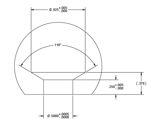
G-050M General Purpose Nozzle styles are commonly used when the formation of a small sprue is acceptable. They are often used when processing filled materials. Because the entire flow path of the nozzle is constructed of hardened tool steel, it is highly resistant to wear. They are also used when it is necessary to gate into a cold runner system. The end of the nozzle is designed to accommodate the machining of a .188 radius through it.
Nozzle Body Section
| Part Number | Length "L" (mm) | Length "L" (in) |
|---|---|---|
| G-050M-3-R2 | 22.225 | 0.875 |
| G-050M-4-R2 | 34.925 | 1.375 |
| G-050M-5-R2 | 47.625 | 1.875 |
| G-050M-6-R2 | 60.325 | 2.375 |
| G-050M-7-R2 | 73.025 | 2.875 |
| G-050M-8-R2 | 85.725 | 3.375 |
| G-050M-9-R2 | 98.425 | 3.875 |
| G-050M-10-R2 | 111.125 | 4.375 |
Gate Well Detail
Minimum Spacing Requirements
NOTE: Nozzle centerlines must be located at least 33mm [1.30″] radially away from the centerline of the nozzle interface.

MS75-G General Purpose Nozzle
Description
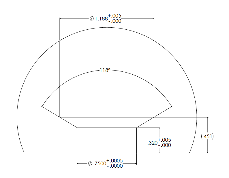
MS75-G General Purpose Nozzles are commonly used when the formation of a small sprue is acceptable. They are often used when processing filled materials. Because the entire flow path of the nozzle is constructed of hardened tool steel, it is highly resistant to wear. They are also used when it is necessary to gate into a cold runner system. The end of the nozzle is designed to accommodate the machining of a .188 radius through it.
Nozzle Body Section

| Part Number | Length "L" (mm) | Length "L" (in) |
|---|---|---|
| MS75-NZ-G3-R2 | 22.2 | 0.875 |
| MS75-NZ-G4-R2 | 34.9 | 1.375 |
| MS75-NZ-G5-R2 | 47.6 | 1.875 |
| MS75-NZ-G6-R2 | 60.3 | 2.375 |
| MS75-NZ-G7-R2 | 73.0 | 2.875 |
| MS75-NZ-G8-R2 | 85.7 | 3.375 |
| MS75-NZ-G9-R2 | 98.4 | 3.875 |
| MS75-NZ-G10-R2 | 111.1 | 4.375 |
| MS75-NZ-G11-R2 | 123.8 | 4.875 |
| MS75-NZ-G12-R2 | 136.5 | 5.375 |
| MS75-NZ-G13-R2 | 149.2 | 5.875 |
| MS75-NZ-G14-R2 | 161.9 | 6.375 |
Gate Well Detail
Minimum Spacing Requirements
NOTE: Nozzle centerlines must be located at least 33mm [1.30″] radially away from the centerline of the nozzle interface.