
Description
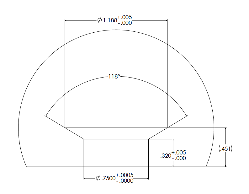
MS75-G General Purpose Nozzle styles are commonly used when the formation of a small sprue is acceptable. They are often used when processing filled materials. Because the entire flow path of the nozzle is constructed of hardened tool steel, it is highly resistant to wear. They are also used when it is necessary to gate into a cold runner system. The end of the nozzle is designed to accommodate the machining of a .188 radius through it. The major flow diameter through the G-075M is .2500″, with .3750″ optional.
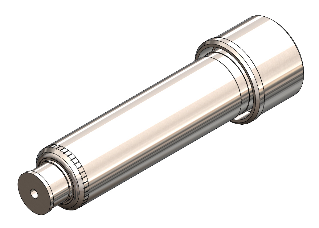
Nozzle Body Section

| Part Number | Length "L" (mm) | Length "L" (in) |
|---|---|---|
| MS75-NZ-G3-R2 | 22.2 | 0.875 |
| MS75-NZ-G4-R2 | 34.9 | 1.375 |
| MS75-NZ-G5-R2 | 47.6 | 1.875 |
| MS75-NZ-G6-R2 | 60.3 | 2.375 |
| MS75-NZ-G7-R2 | 73.0 | 2.875 |
| MS75-NZ-G8-R2 | 85.7 | 3.375 |
| MS75-NZ-G9-R2 | 98.4 | 3.875 |
| MS75-NZ-G10-R2 | 111.1 | 4.375 |
| MS75-NZ-G11-R2 | 123.8 | 4.875 |
| MS75-NZ-G12-R2 | 136.5 | 5.375 |
| MS75-NZ-G13-R2 | 149.2 | 5.875 |
| MS75-NZ-G14-R2 | 161.9 | 6.375 |
Gate Well Detail
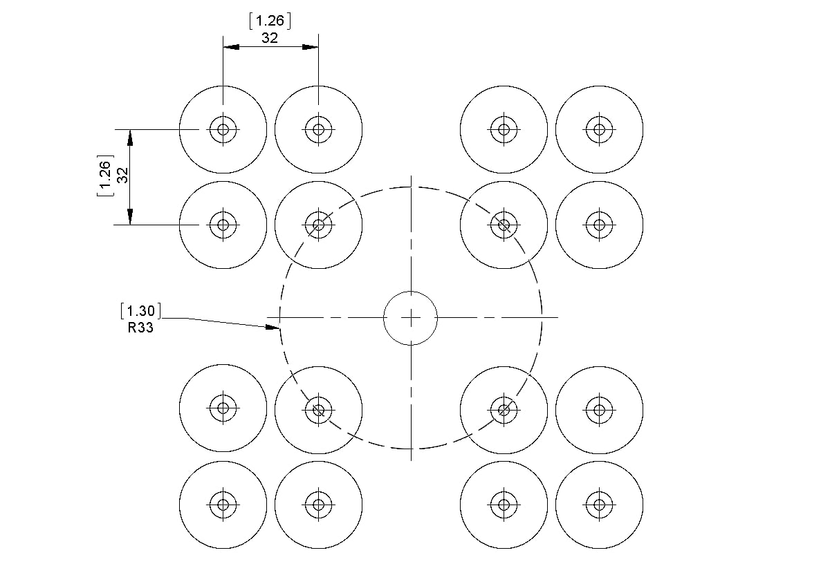
Minimum Spacing Requirements
NOTE: Nozzle centerlines must be located at least 33mm [1.30″] radially away from the centerline of the nozzle interface.