Description
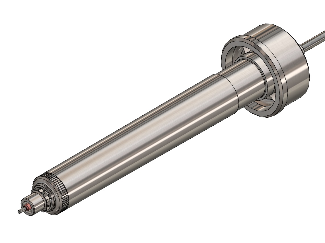
M10VG Valve Gate Nozzle eliminates the gate vestige. They are used when it is necessary to gate directly into the part being molded without leaving a vestige. The valve gate nozzle features a field replaceable tip that can be easily changed by the customer if necessary. It performs well when processing unfilled, low temperature resins and is best for part sizes up to 5 grams. The valve pins can be actuated by pneumatics or hydraulics.
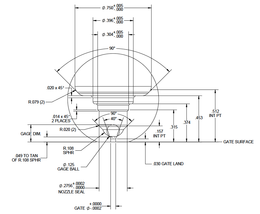
When using the valve gate nozzle, all necessary tip clearances are machined into the mold cavity by the customer. This method allows for the smallest witness mark to be left on the part after molding. The valve gate pin mark will resemble an ejector pin mark on the part.
Polyshot Accutrak Technology
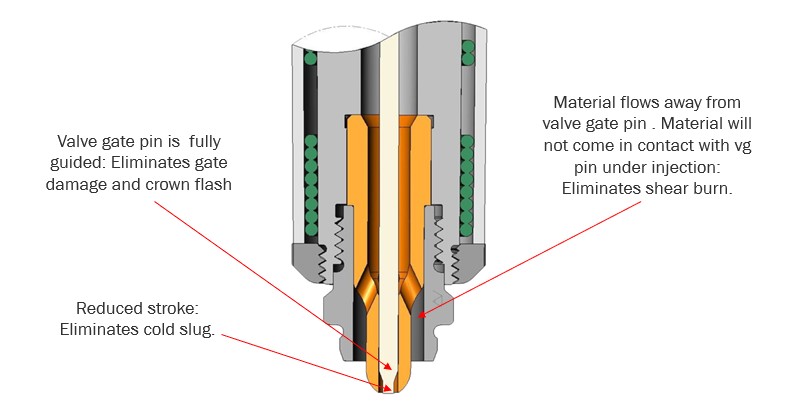
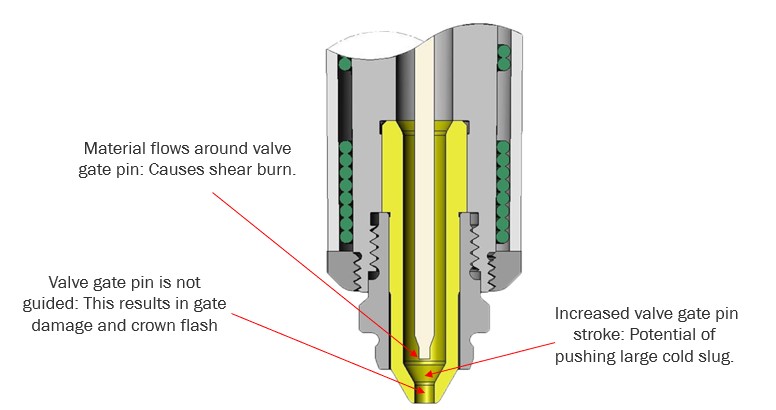
Polyshot Accutrak Technology was developed to improve product quality in injection molded parts. The Accutrak design allows for quick and easy color changes. This reduces waste and down time.
Features include:
Burn-free gates, no black specks or streaks | Completely sweeps the gate well area clean each slot | Valve gate versions offer very short stroke reducing the hydraulic action in the gate area | Valve pin stays fully engaged and guided 100% of the time | Pinpoint style Accutraks are also available
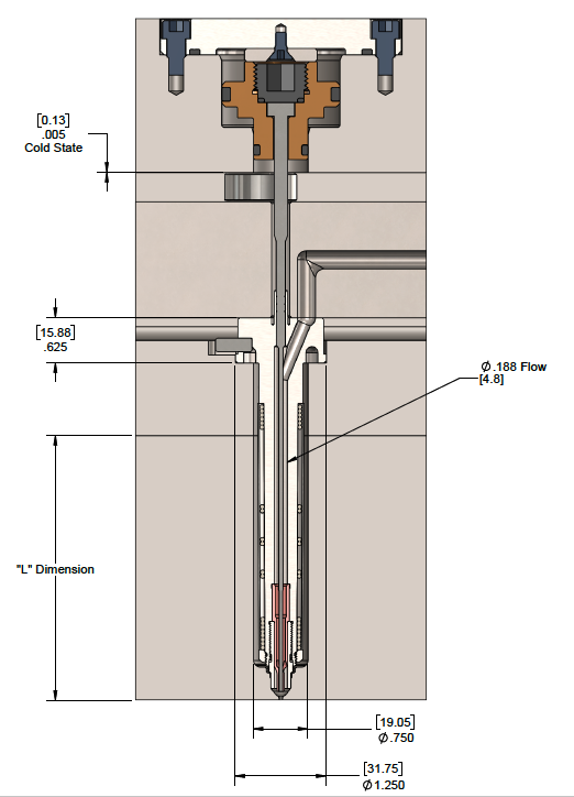
Nozzle Body Section
Gate Well Detail
| Gate Ø | Gage Dimension |
|---|---|
| 0.025 | 0.1726 |
| 0.026 | 0.1725 |
| 0.027 | 0.1724 |
| 0.028 | 0.1723 |
| 0.029 | 0.1722 |
| 0.030 | 0.1721 |
| 0.031 | 0.1720 |
| 0.032 | 0.1719 |
| 0.033 | 0.1718 |
| 0.034 | 0.1717 |
| 0.035 | 0.1716 |
| 0.036 | 0.1715 |
| 0.037 | 0.1714 |
| Gate Ø | Gage Dimension |
|---|---|
| 0.038 | 0.1713 |
| 0.039 | 0.1711 |
| 0.040 | 0.1710 |
| 0.041 | 0.1709 |
| 0.042 | 0.1707 |
| 0.043 | 0.1706 |
| 0.044 | 0.1704 |
| 0.045 | 0.1703 |
| 0.046 | 0.1701 |
| 0.047 | 0.1700 |
| 0.048 | 0.1698 |
| 0.049 | 0.1696 |
| 0.050 | 0.1695 |


